Recently, I have been designing some SMPS and required some hardware to measure the actual loop response of the complete converters. People familiar with this area will probably know this can be done breaking the feedback loop of the converter and injecting a small AC signal and measuring the loop response at the output of the converter. However, such a measurement requires a mechanism to inject this signal differential across a small resistor inline with the normal feedback network. Unfortunately, as most signal generators are ground referenced we need special hardware to convert this output to a floating output.
Commercial PSU analysers come with expensive injection transformers that allow us to do that. These transformers are designed to have a very flat response in the region of conventional loop bandwidths of SMPS converters, these range from a few Hz to upto a few MHz.
For example this transformer for the Bode-100 costs $500!

The reason these transformers are so expensive is the use of exotic cores that result in high inductance with minimum turns. This way the low frequency behaviour of the transformer is improved without degrading the high frequency. Simply speaking, we need to add more turns to the transformer to improve low frequency behaviour, but the increased parasitic capacitance then degrades the high frequency behaviour.
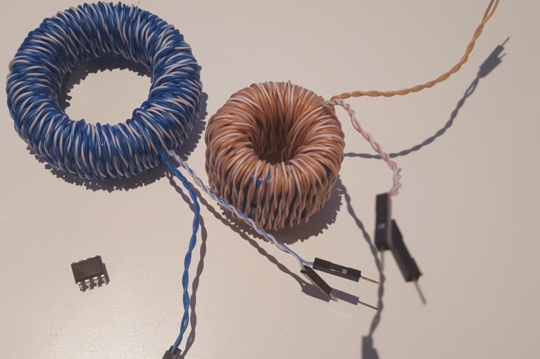
I experimented with a few DIY transformers by purchasing some cheap £10 cores from RS. I wound around 5m of differential cabling scavenged from an old Ethernet cable.
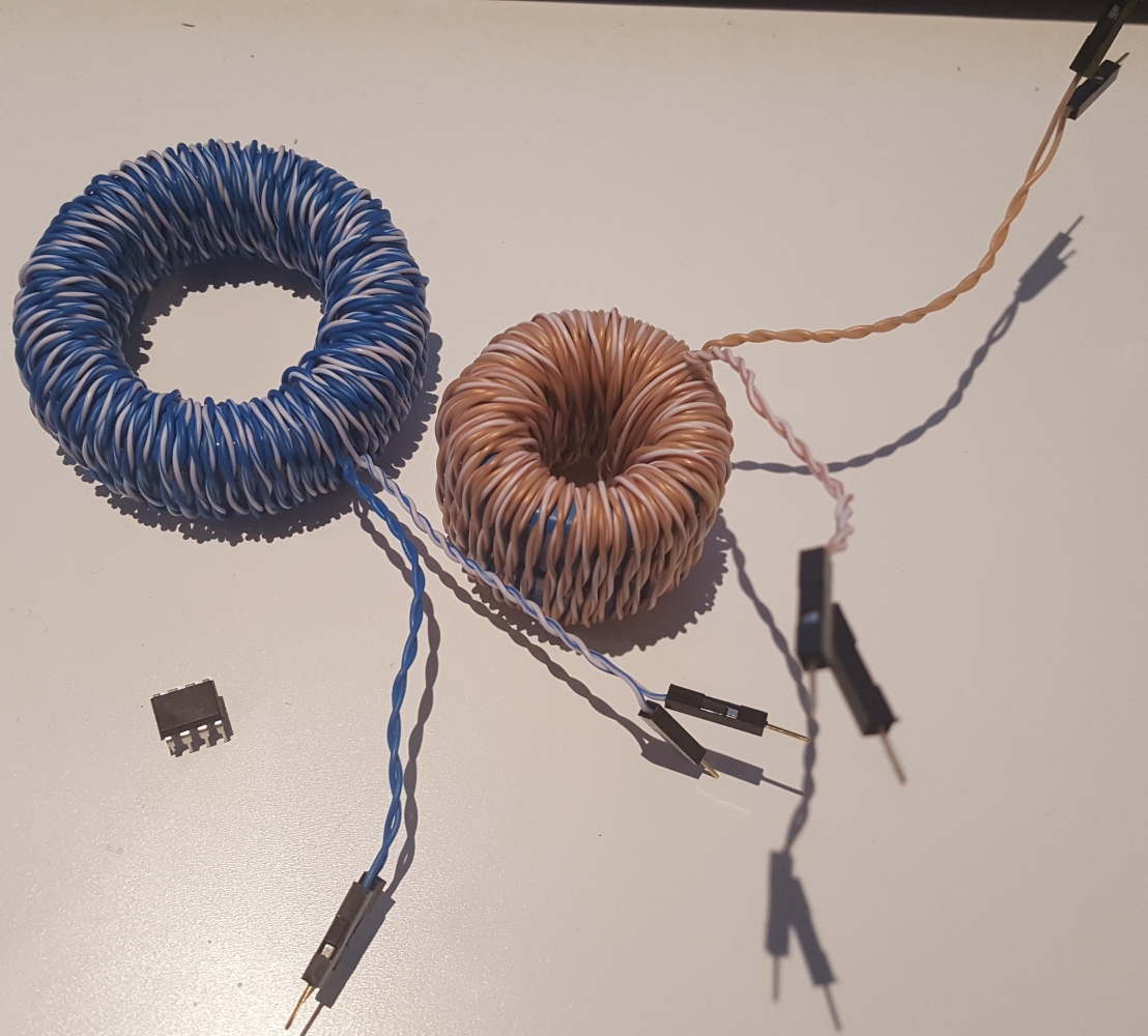
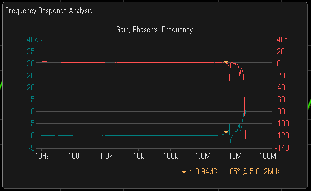
The results are surprisingly flat, and both transformers work well from about 10 Hz upto 5 MHz, and should be usable upto 10 MHz. Not bad for £10!

What type of core did you used?
LikeLike
EPCOS B64290L0040X830 and EPCOS B64290L0674X038
LikeLike
It is N30 material soft ferrite, initial u=4300
Click to access pdf-n30.pdf
LikeLike
I had made a toy network analyzer. I will try your design to give my project a more practical form: –
https://sites.google.com/site/hobbydebraj/bode-analyzer-using-stm32f407
LikeLike
Very interesting. Have a look at my other project which is an LCR meter (i.e bode plot). I see most of your calculations were based in the time domain where as I took a freq domain approach. Super cool!
LikeLike
Do you have the plot for the second transformer? how do they compare?
LikeLike
They were essentially identical. One version used a larger core whereas the other used a stack of smaller cores, both had same number of turns so frequency response came out more or less equal..
LikeLike
Hi Adilmalikn! I’m following in your footsteps. How did you test the response gain/phase of your transformer? I wanted to verify my coil as well. Thanks! 🙂
LikeLike
I used my keysight scope (1000 X series) which has a inbuilt bode plot function. You can just use a 2 channel scope, with one probe connected to each side of the transformer. Eyeballing the relative amplitude and phase should then be sufficient!
LikeLike